Deltarobot kinematics
The Delta robot is one of the most popular parallel robots in industrial use today.Typically a parallel robot is designed such that all actuators remain fixed to the support structure of the robot thereby minimising the mass of the moving parts of the robot and enabling very fast accelerations. The following video shows a simplified delta robots kinematics equations.
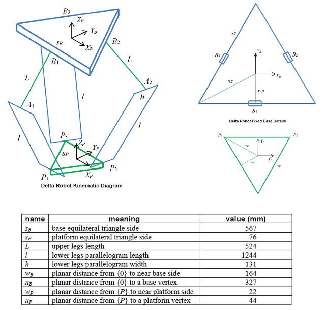
Since the project was quite complicated regarding mechanical design, I have been strongly advised by the instrctors to quickly start with the mechanichal design of the project to make a primary draft of the full body. First, I made a research to find about the geometric design and kinematics of the delta robots and found this paper as a good reference considering the following diagram and measurements ratios. There were many good examples and videos that helped me to find more about the details of the structure.
3D design in Fusion 360
I started with a simple sketch of the fiber clamp and then, developed the design by adding other components by using some Fusion features including Extrude, Hole, Fillet, Chamfer and Joint.
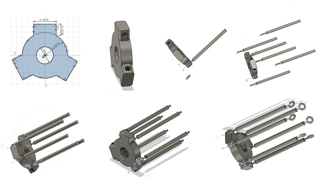
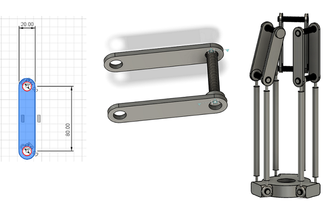
Figure 1. Developing the first draft of the full design of delta robot.
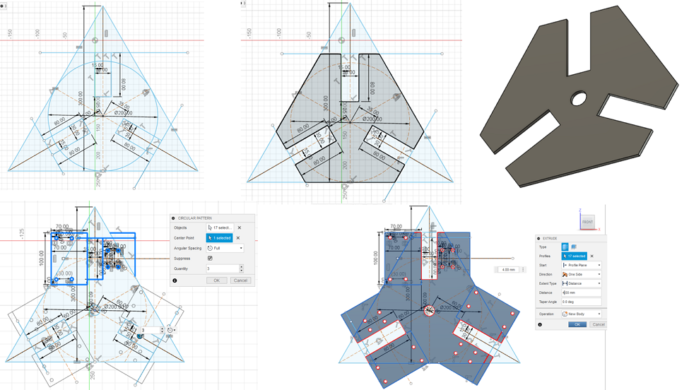
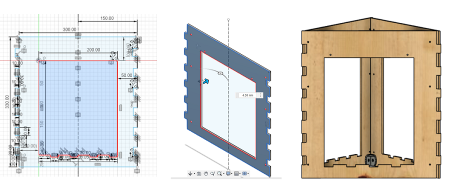
Figure 2. 3D design for the upper plate for holding the stepper motors.
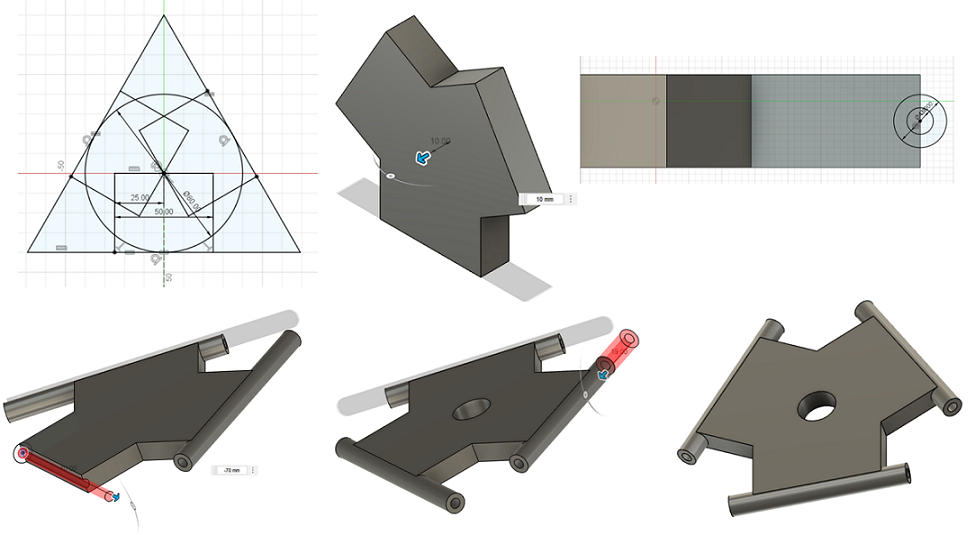
Figure 3. 3D design of the lower plate for holding the optical fiber.
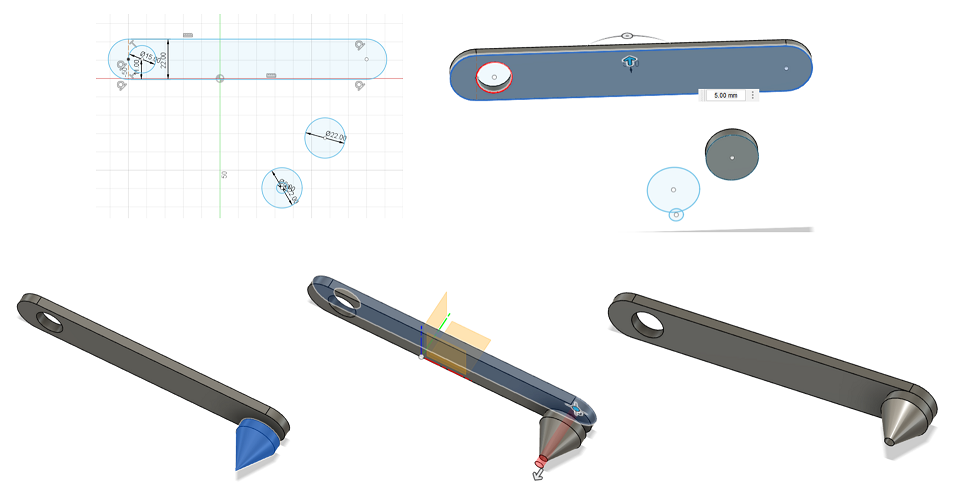
Figure 4. 3D design of the upper arm.
Figure 5. 3D design of the joint for the upper plate.
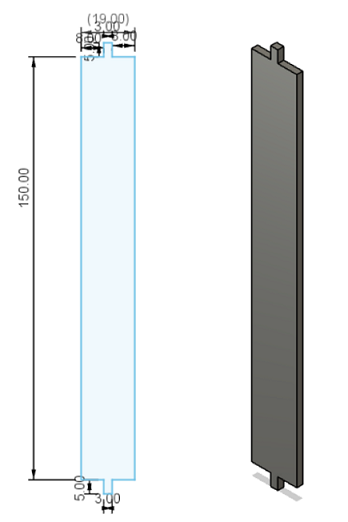
Figure 6. 3D design of the lower arm.
Then, I came to the most important part of the mechanical design of my project which was rod end bearings which are used on the ends of cylinders, linkages, rods, and shafts to take up angular misalignment between connected parts. They consist of a spherically-shaped inner ring and a cylindrical bore for shaft mounting. First I searched in the fablab inventory, but the instructors insured me that it was not available there. So, we had to order it from Amazon which naturally, it would take a few days to arrive. So, to prepare a first version of the mechanical design, I tried to find the 3d desing on the internet to find free models and found a rod end model file and then, added a sphere with a 4mm hole and thread while using the joint feature and choosing Ball as the type of Motion.

Figure 7. 3D design of the rod end bearing.
3D printing with Stratasys Fortus 380mc
I used Stratasys Fortus 380mc 3D printer for lower and upper plates, upper arms and rod end bearings.
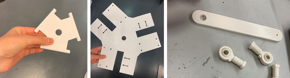
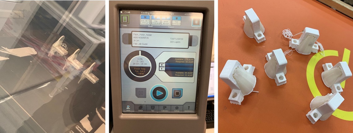
Figure 8. 3D printed of the designed components.
But the rod end bearings did not have a good quality and the inner ball was stucked to the ring and could move and also, the size of the hole did not fit the bar joint (wrong design). But with the help of Juha-Pekka, I did a few post-precossing steps to solve the problem. First, I used hammer to loose the ball inside the ring and then, add tube joints to put inside the hole to fix the extra size.
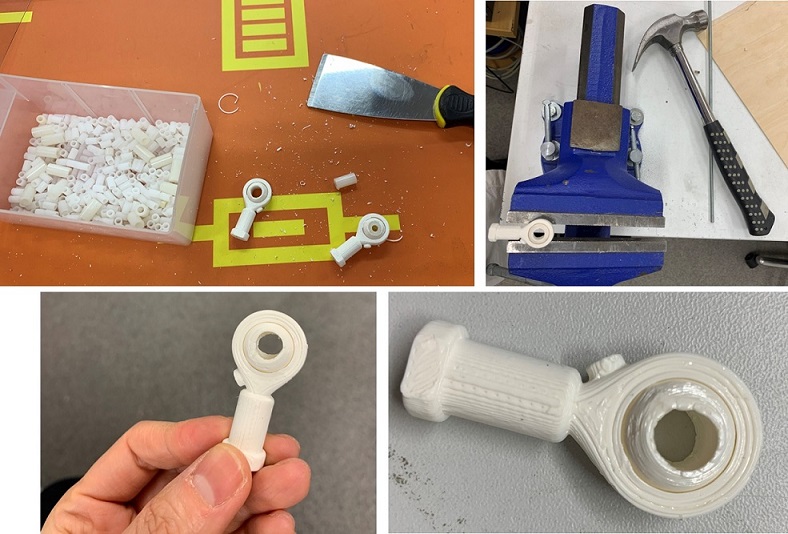
Figure 9. post-processing steps for rod end bearings.
Laser citting with Epilog Fusion M2 40 Laser
I had the lower arms design to be cut with the laser cutter. I tested Acrylic as the material to see how it would work. But the slot was broken after a few rotation with the rod end.
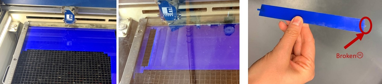
Figure 10. Laser cutting the lower arm with with Acrylic.
So, I came back with the safe option (plywood 3 mm) and prepared the lower arms.
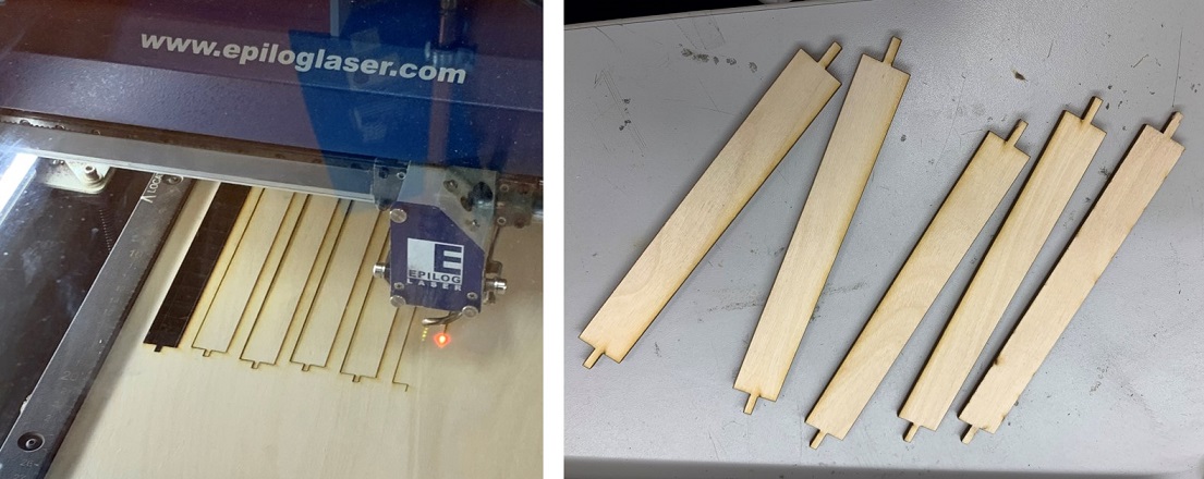
Figure 11. Laser cutting the lower arm with plywood .
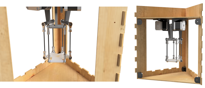
Assembling the components
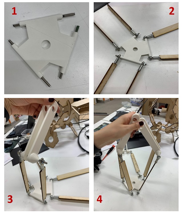
Next, I started the interesting part of the mechanical design which is assembling different parts and find the bugs of the design.
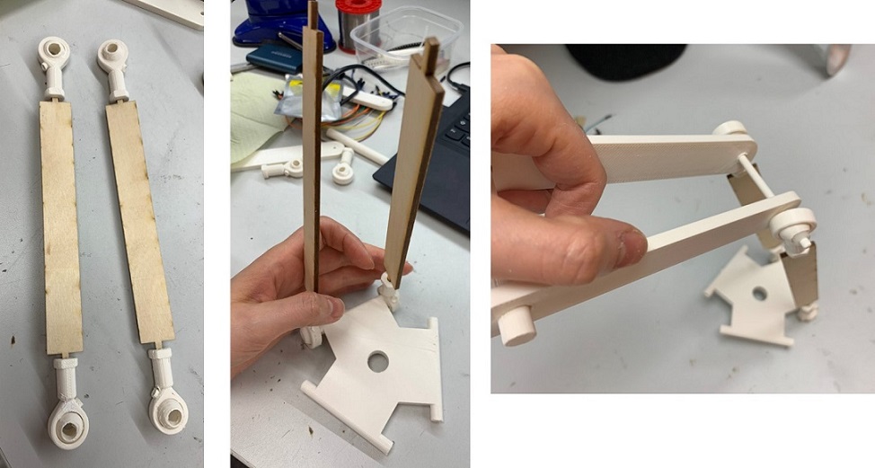
Figure 12. Assembling the parts.
It was fine for the first stage but the design needed some improvements in addition to the replacement of the rod end bearings with the steel ones which had been ordered.
After a couple of days, the metal rod end bearings were arrived and I could test the design with them.
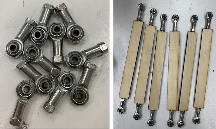
Figure 13. Ordered metal rod end bearings and assembling them with the rest of components.
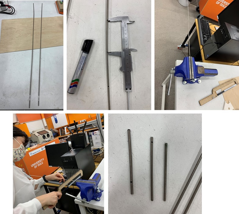
After discussing with the local instructors, I realized it would be better to use a threaded rod for the bearings joint. So, I had to visit a local shop to buy 4mm aluminum threaded rod. Then, I measured the joint length I needed and cut the rod with a saw.
Then, I tried to assemble the parts starting from the lower plate, then lower arms and finally the upper arms.
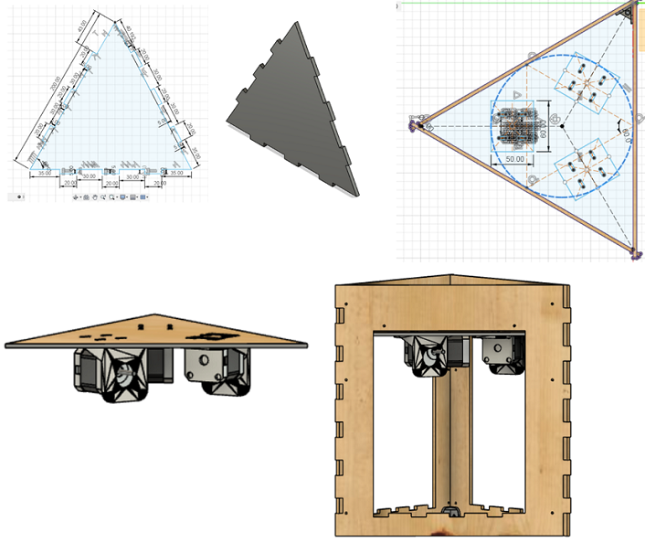
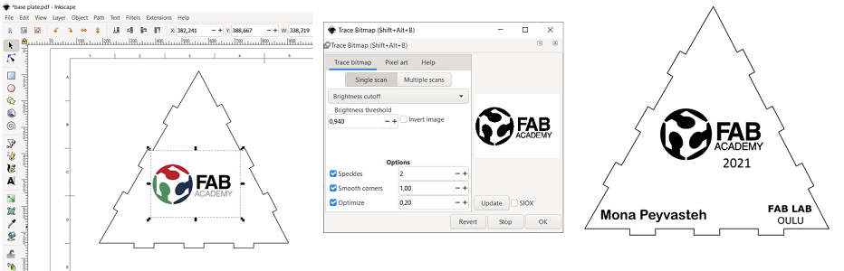
Next, I started to design a frame for the deltabot with upper and lower plates for holding motors and sample.
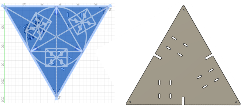
Then, a few 2D design with Inkspace to customize my deltabot!:)
Correction phase
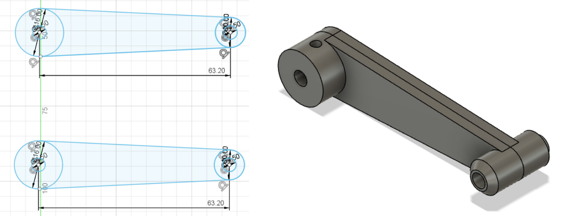
After the first assembling try, I found the mechanical bugs of the body and designed a new shorter upper arm to be connected to the shafts of the motors.
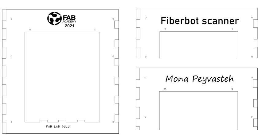
Also, for system integration and packaging, I needed to make holes on the frames for attaching the boards and redesign them.
And again, I srated assembling the full body with the corrected designs.